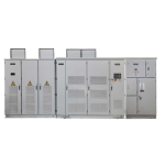
| Performance |
Specifications
|
| Device Input |
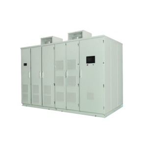
MV Transformer (Medium Voltage Transformer) |
Air-cooled dry-type transformer with 18 to 54 pulse output, depending on the network voltage level, and an auxiliary winding to supply three-phase control voltage plus neutral. |
| Input Voltage |
Three-Phase 3.3 kV ~ 11 kV (−15% ~ +5%) |
| Input Current |
According to the device rating |
| Input Frequency |
Permissible Frequency: 50 Hz or 60 Hz (±10%) |
| Power Factor Correction |
0.96 < |
| Efficiency |
Inverter Section Efficiency: >98% (Overall Transformer and Inverter Efficiency: >95%) |
| Input Harmonics |
Compliance with IEEE 519 Standard |
| Voltage Sag Ride-Through Threshold |
Five Cycles |
| Control Power Supply |
380VAC (3Ph+N) |
| Live Supply |
For PLC and Control Section: 110–240 V AC/DC |
Device Output
|
Waveform Generation Technique |
Low-Voltage Power Cells with Cascaded H-Bridge Multilevel Configuration |
| Modulation Technique |
SVPWM, SPWM (for Scalar and Vector Control) |
| Output Voltage |
0 to Rated Input Voltage |
| Output Frequency |
0~80Hz |
| Frequency Resolution |
0.01Hz |
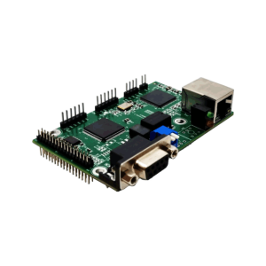
| PLC Control Section |
Siemens S7-200 Smart |
| Central Microcontroller |
32-bit Texas DSP and FPGA |
Installation Environment
|
Operating Ambient Temperature |
0 ~ 40 ºC (up to 45 ºC with derating) |
| Transport Ambient Temperature |
-10 ~ 70 ºC, Non-Condensing |
| Storage Ambient Temperature |
-10 ~ 60 ºC, Non-Condensing |
| Humidity |
Non-Condensing, Up to 90% Maximum Humidity |
| Installation and Maintenance Conditions |
Enclosed Space with Controlled Ambient Temperature (Indoor) |
| Installation Altitude |
Below 1500 m; above this, power is reduced by 1% for every 100 m up to 3000 m. |
| Drive Cooling |
Forced Air Cooling with Fan |
| Dust |
Free of conductive and corrosive dust, <6.5 mg/dm³ |
| Product Color |
RAL7032 |
| Enclosure Protection (IP) |
IP30 |