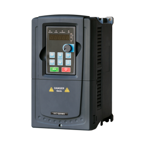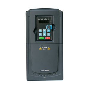
VX7 Series
The VX7 series drives offer speed control for both asynchronous and synchronous motors, with the option to install encoders on the motor, providing high speed and torque control. Using advanced DSP microcontrollers, these drives support precise speed adjustment and position control for CNC applications with various encoders and synchronous motors.

- 33 years of manufacturing experience.
- An annual production capacity of 40,000 units.
- The largest drive manufacturer in the Middle East.
- Certified as a Knowledge-Based Company by the Vice-Presidency for Science and Technology.
- CE Certificate of the European Community.
Compatible with Various Motor Types
Capable of driving various types of motors: high-speed motors, spindle motors, variable-frequency motors, asynchronous servo motors, and permanent magnet (PM) synchronous motors.
Closed-Loop Vector Control
Enhanced torque, speed, and position control for higher precision and performance
Position Control: Suitable for machine positioning applications
Torque and speed control to ensure stable motor performance and rapid response with minimal torque fluctuations
Excellent magnetizing control capability to meet acceleration and deceleration requirements
Flying Start Control
Special Functionality for Machine Tools
Precise Spindle Stop: For spindle position control, featuring 7 adjustable positions and 4 reference positions
High-Power Servo Motor Control
Torque adjustment capability in the field-weakening region for electric vehicles
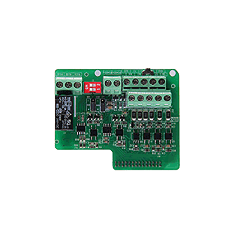
Supports Endat, Sin/Cos, UVW, Incremental, and Resolver Encoders
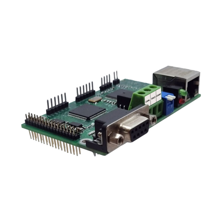
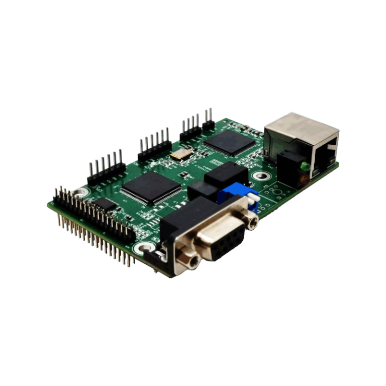
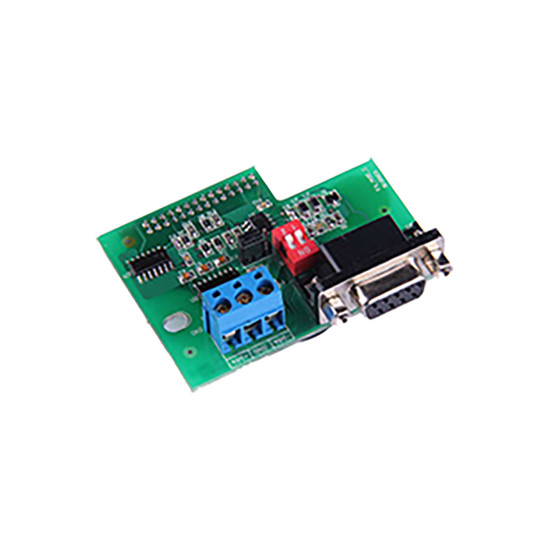
Advanced Communication Networks
MODBUS RS485
PROFIBUS (Optional)
•Optional) CANopen)
Analog Speed Control and Position Control
Speed Control: The spindle servo motor speed can be smoothly and precisely adjusted via a voltage or analog command provided by the user.
Positioning Function: Select the target position via a combination of positioning terminals and initiate the positioning process through "Spindle Positioning / Return to Zero."
Pulse and Photoelectric Positioning
The spindle position and rotation direction can be controlled via two square-pulse commands with a 90° phase difference using a CNC system. Switching from position control to speed control is also possible.
|
Performance |
Specifications |
|
|---|---|---|
|
Inverter Input |
Device Power |
2.2kW ~ 500kW |
|
Input Voltage |
Three-Phase AC 3PH 400V ±10% |
|
|
Input Current |
According to the device rating |
|
|
Input Frequency |
Permissible Range 47~63Hz |
|
|
Filter EMC |
Conducted and radiated noise of all devices complies with standards IEC61800-3 C3 Compliance with Current Bypass Jumper in All Devices EMC For Power Supply System IT In Class II Environments With high ground impedance, where leakage current to ground may cause system trips An EMC bypass jumper is provided Standard IEC61800-3 C2 In Class I environments, an external filter is required EMC is |
|
|
Harmonic Filter |
For ratings above 400 kW, a three-phase line reactor is included. |
|
|
Inverter Output |
Output Voltage |
0~400 Volt |
|
Output Frequency |
0~400Hz |
|
|
Overload Capacity Heavy duty |
150% of Rated Current: 1 minute per 10 minutes 180% of Rated Current: 10 seconds 200% of Rated Current: 1 second |
|
|
Output Frequency Adjustment |
Digital potentiometer, analog input, pulse frequency adjustment, multi-step speed setting, configuration PLC Simple Configuration PID Communication Configuration MODBUS and PROFIBUS and CANOPEN Speed can be set using combined modes: addition, subtraction, maximum, or minimum Speed Adjustment via Switches UP and or Down and combined with reference inputs |
|
|
Dynamic Braking Unit |
Brake Unit for Ratings up to 30kw The brake is built-in for lower power ratings and can be installed externally for higher power ratings. |
|
|
Control Technology |
Control Mode |
SVPWM, SVC, VC (Scalar Mode and Vector Control – Closed-Loop and Open-Loop) |
|
Engine Type |
Asynchronous and Permanent MagnetSynchronousPMSMand High-Power Servo Motors (with Encoders SIN/COS ) |
|
|
Adjustable Speed Ratio |
Asynchronous Motor 1:200(SVC) and Synchronous Motor 1:20(SVC) and in Closed-Loop Mode 1:1000 (VC) |
|
|
Adjustable Speed Accuracy |
±0.2%(SVC) and in Closed-Loop Mode (VC) Value ±0.02% |
|
|
Speed Fluctuation |
+0.3%(SVC) |
|
|
Torque Response |
20ms> in Vector Control Mode and Closed-Loop Vector Control (VC) <10ms |
|
|
Torque Accuracy |
10% in Sensorless Vector Control Mode |
|
|
Starting Torque |
Asynchronous Motor 0.25Hz/150% (SVC) and Synchronous Motor 2.5 Hz/150%(SVC) in Closed-Loop Mode 0Hz/150%(VC) |
|
|
Switching Frequency |
1.2~15kHz (Factory preset according to the drive power rating) |
|
|
Network Communication |
MODBUS Standard on the inverter I/O card PROFIBUS card equipped with an Ethernet input for monitoring ( Optional Card) Card CANOPEN As an Option |
|
|
Acceleration and Deceleration |
Linear and Curved Quadratic S Shape and selection of four acceleration levels via two digital inputs |
|
|
Control Panel |
The inverter panel is detachable for mounting on control panels |
|
|
Fault Protection |
Fault Protection: Over 30 functions including overvoltage, undervoltage, overheating, input/output phase loss, ground fault, output short circuit, inverter/motor overload, and sudden load reduction (e.g., belt breakage, dry-running pump). |
|
|
Control Inputs and Outpu |
Analog Input |
Two Channels (AI1, AI2) 0~10V/0~20mA and One Channel (AI3) -10V~+10V Analog Signal Voltage Detection ≤20mV |
|
Analog Output |
Two Channels (AO1, AO2) 0~10V/0~20mA |
|
|
Digital Input |
Eight Input Channels with Internal Impedance 3.3kΩand one high-speed pulse channel up to a maximum of 50kHz Pulse Speed Response Detection ≤2ms |
|
|
Digital Output |
One High-Speed Pulse Channel and One Transistor Output Open collector |
|
|
Relay Output |
Two Programmable Relay Outputs with Specifications 3A/ AC250V, 1A/ 30VDC Common Terminal, Normally Closed (NC)NC) و باز (NO) Relay 1: RO1A NO, RO1B NC, RO1C Relay 2: RO2A NO, RO2B NC, RO2C |
|
|
|
Encoder |
Equipped with an Encoder Card Standard Pulse (up to 100kHz ) and Encoder Card SIN/COS As an Option |
|
Installation Environment |
Mounting Method |
Wall-mountable, flange-mountable, and for higher kW ratings, can be installed as a standalone panel (Stand aloneis |
|
Ambient Installation Temperature |
-10°C ~ +50°C : Device rated power based on maximum 40°C Designed for a maximum ambient temperature of 40 °C. For temperatures above 40 °C up to 50 °C, derate by 1.5% for each additional degree Celsius. Capacity reduction should be considered |
|
|
Enclosure Protection |
IP20 |
|
|
Cooling |
Forced Air Cooling via Fan |
|
|
Device Software Functions |
Dual Motor Identification Function (Motor 1 and Motor 2) |
After entering the motor nameplate parameters, this function measures the motor’s electrical parameters either statically or dynamically, registers them in the inverter, and uses them for vector control calculation functions. In the [Series Name] Drive VX60 Two complete sets of motor parameters are provided and can be selected via a digital switch. |
|
Spindle Stop Function |
Four zero positions and seven reference positions |
|
|
Position Reference |
External reference setting capability via switch or pulse position Z Encoder |
|
|
Servo Control |
Shaft Position Control via Pulse Counting |
|
|
Pulse Division Function |
Pulse Output for Speed Control According to the Defined Divider |
|
|
Flux Control Adjustment Function in the Field Weakening Region |
Flux Control Adjustment Function in the Field Weakening Region |
|
|
Friction Torque Function |
Torque Compensation Coefficients at Low and High Speeds |
|
|
Function AVR for Energy Saving |
In applications with light-load conditions, it can reduce network energy consumption by lowering the voltage. Additionally, in networks with fluctuating voltage, it automatically stabilizes the voltage. |
|
|
Speed or Position Mode Selection ( position control ) |
via Digital Input |
|
|
Speed Tracking Function |
This function is designed for rotating loads. For such loads, the inverter first detects the rotational speed and then brings the motor to the requested speed. |
|
|
Length Measurement Function |
This function operates in pulse-counting mode |
|
|
Braking Function DC and Magnetization |
This function features adjustable braking time DC It operates at the beginning of motor start or stop. In addition, the magnetization function pre-magnetizes the motor core before startup to ensure high starting torque. |
|
|
Integrator Function |
This function can adjust the speed control according to the process variable. The feedback input of this integrator can be analog, digital, or via Modbus network. It also includes an integration stop or Pause has also been provided |
|
|
Vector Control Integrator Functions |
Regulator and integrator settings of the vector control algorithm, including speed loop and current loop |
|
|
Step Speed Function |
This function allows selection of up to sixteen preset speeds using four digital inputs. |
|
|
Function PLC ساده |
With this PLC You can repeat sixteen speeds and four types of acceleration within a specified time. |
|
|
Frequency Window Function |
Frequency windows allow the activation of auxiliary processes. |
|
|
Pulse Counter Function |
This function is designed to compare the number of input pulses with two preset digital values and generate a digital output accordingly. |
|
|
Digital Input Function |
Program 40 Type of Function and Hardware Activation as Active high and or Active low and also allows software activation of the function as 1 or 0 is also possible. In addition, it supports programming of on/off delay for the inputs. Capability for Commands On/Off and Forward/Reverse Joystick |
|
|
Digital Output Function |
Programmable 28 Types of Functions with Hardware Activation as Active high and or Active low Additionally, it allows programming of delay on make or break of outputs. |
|
|
Torque Control Function |
Adjustable via Analog and Pulse Digital Inputs HDI and Modbus and PROFIBUS Motor Torque and Braking Torque Upper Limit Settings Capable of operating in both torque mode and speed control mode in processes via digital input |
|
|
Motor Vibration Control Function |
This function allows different settings for low and high frequencies. |
|
|
|
Functions for Setting Scalar or SVPWM |
Capability to Set Five Types of Curves V/f with slip compensation gain and torque boost at low frequencies |
|
Independent Voltage and Frequency Control Function |
with slip compensation gain and torque boost at low frequencies HDI and communication networks in scalar mode |
|
|
Frequency Jump Function |
Mechanical Vibration Frequency Passing Function |
|
|
Monitoring Functions |
Over 40 Types of Monitorable Drive Parameters for Monitoring and Troubleshooting |
|
|
Standards |
IEC61800-2 and IEC61800-5-1 included: Voltage and torque and current rating Frequency and speed range Overcurrent/over Torque capability Power factor measurement Voltage division Checking of protective measures Properties under unusual service conditions Audible noise Steady state performance and temperature rise DC voltage test IEC 61000-4-2 immunity to electrostatic discharge IEC 61000-4-3 immunity to radiated electromagnetic fields IEC 61000-4-4 immunity to electrical fast transient/burst IEC 61000-4-5 immunity to surge IEC 61000-4-6 immunity to conducted disturbances induced by radio frequency fields IEC 61000-4-8 immunity to power frequency magnetic field |
|